- 您现在的位置:买卖IC网 > Sheet目录1193 > AC164130 (Microchip Technology)BOARD DAUGHT PICTL PLUS ECAN/LIN
�� �
�
�Introduction�
�1.2�
�FUNCTIONAL� OVERVIEW�
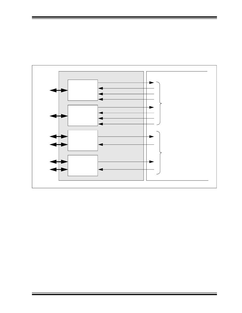
�The� block� diagram� shown� in� Figure� 1-3� illustrates� the� mainstream� operation� of� the�
�CAN/LIN/J2602� PICtail?� (Plus)� Daughter� Board.� The� board� contains� two� LIN� signal�
�conditioning� circuits� and� two� CAN� signal� conditioning� circuits.� The� board� also� enables�
�power� to� be� provided� by� the� development� board� it� is� connected� to,� or� by� an� external�
�12V� DC� source.�
�FIGURE� 1-3:�
�CAN/LIN/J2602� PICtail� ?� (Plus)� DAUGHTER� BOARD� BLOCK� DIAGRAM�
�CAN/LIN/J2602� PICtail� ?� (Plus)� DAUGHTER� BOARD�
�Receive�
�DEVELOPMENT� BOARD�
�LIN1�
�Bus�
�LIN2�
�Bus�
�LIN1�
�Transceiver�
�(U1)�
�LIN2�
�Transceiver�
�(U2)�
�Transmit� Enable�
�Transmit�
�Interrupt/Wake�
�Receive�
�Transmit� Enable�
�Transmit�
�Interrupt/Wake�
�To� UART� Module� on�
�dsPIC33F,� PIC24� or� PIC18�
�CAN1�
�Bus�
�High�
�Low�
�CAN1�
�Transceiver�
�(U3)�
�Receive�
�Transmit�
�To� ECAN� Module� on�
�CAN2�
�Bus�
�High�
�Low�
�CAN2�
�Transceiver�
�(U4)�
�Receive�
�Transmit�
�dsPIC33F,� PIC24� or� PIC18�
�1.2.1�
�LIN� Operation�
�The� CAN/LIN/J2602� PICtail?� (Plus)� Daughter� Board� connects� two� LIN� transceivers�
�with� integrated� voltage� regulators� to� UART� modules� on� a� dsPIC33F,� PIC24� or� PIC18�
�control� device� on� the� Explorer� 16� or� PIC18� Explorer� Board.� The� LIN� transceiver� moni-�
�tors� the� LIN� bus,� conditions� the� incoming� signal� and� passes� it� to� the� UART� module� on�
�the� control� device.� The� LIN� transceiver� responds� to� a� “Transmit� Enable”� from� the� con-�
�trol� device� by� conditioning� an� output� signal� and� placing� it� on� the� LIN� bus.�
�A� Power-down� mode� turns� the� transmitter� and� voltage� regulator� off,� leaving� only� the�
�receiver� and� wake-up� circuits� in� operation.� Each� LIN� circuit� includes� a� Master/Slave�
�jumper� to� accommodate� a� Master� node� on� the� LIN� bus.�
�In� order� to� use� the� transmit� enable� for� the� LIN2� transceiver� with� the� PIC18� Explorer�
�Board� and� a� PIC18� device,� the� LIN2TXE� pin� must� be� connected� to� 5V,� or� a� pin� on� the�
�PIC18� device,� to� control� it.� This� can� be� done� by� connecting� a� jumper� wire� on� the� J18�
�header� between� LIN2TXE� and� either� the� 5V� supply� also� on� the� J18� header,� or� an� avail-�
�able� pin� on� either� the� J17� or� J18� header.� For� more� information� on� the� J17� and� J18�
��?� 2011� Microchip� Technology� Inc.�
�DS70319B-page� 13�
�发布紧急采购,3分钟左右您将得到回复。
相关PDF资料
AC164131
BOARD DAUGHTER USB PICTAIL PLUS
AC164132
BOARD DAUGHTER PICTAIL ETHERNET
AC164141
BOARD SMART CARD / SIM CARD
AC164142
BOARD DAUGHTER PWR LINE MODEM
AC164144
LLC PICTAIL PLUS DAUGHTR BRD
AC164145
BOARD DAUGHTER PWR LINE MODEM
AC243005-1
KIT MEMORY SERIAL SUPERFLASH 1
AC244002
PAK PERFORMANCE MPLAB REAL ICE
相关代理商/技术参数
AC164130-2
功能描述:子卡和OEM板 CAN/LIN PICtail Plus Daughter Board RoHS:否 制造商:BeagleBoard by CircuitCo 产品:BeagleBone LCD4 Boards 用于:BeagleBone - BB-Bone - Open Source Development Kit
AC164131
功能描述:子卡和OEM板 USB PICtail Plus Daughter Board RoHS:否 制造商:BeagleBoard by CircuitCo 产品:BeagleBone LCD4 Boards 用于:BeagleBone - BB-Bone - Open Source Development Kit
AC164132
功能描述:以太网开发工具 100Mbps Ethernet PICtail Plus DB
RoHS:否 制造商:Micrel 产品:Evaluation Boards 类型:Ethernet Transceivers 工具用于评估:KSZ8873RLL 接口类型:RMII 工作电源电压:
AC164133
功能描述:电源管理IC开发工具 dsPIC BuckBoost PICtail Daughtr Brd RoHS:否 制造商:Maxim Integrated 产品:Evaluation Kits 类型:Battery Management 工具用于评估:MAX17710GB 输入电压: 输出电压:1.8 V
AC164133
制造商:Microchip Technology Inc 功能描述:Buck/Boost Converter PICtail P
AC164133-DM300027
制造商:Microchip Technology Inc 功能描述:DIGITAL POWER WEB BUNDLE 制造商:Microchip Technology Inc 功能描述:DIGITAL PWR SUPPLY BUNDLE, DEV KIT 制造商:Microchip Technology Inc 功能描述:EVAL KIT, DIGITAL POWER SUPPLY BUNDLE; Silicon Manufacturer:Microchip; Silicon Core Number:dsPIC33FJ16GS; Kit Application Type:Power Management; Application Sub Type:Power Supply Controller ;RoHS Compliant: Yes
AC164134
功能描述:Zigbee/802.15.4开发工具 PICtail Plus RF Card RoHS:否 制造商:Silicon Labs 产品:Development Kits 工具用于评估:EM35x 频率:2.4 GHz 接口类型:USB 工作电源电压:
AC164134-1
功能描述:子卡和OEM板 PICTail Plus 2.4GHz RF Card RoHS:否 制造商:BeagleBoard by CircuitCo 产品:BeagleBone LCD4 Boards 用于:BeagleBone - BB-Bone - Open Source Development Kit